|
Vintage television:Universal Video Board-kit for Suppression of Vertical Retrace LinesDarius-K. Mottaghian-Milani |
|
Fernseher und Farbfernseher aus der Anfangzeit des Fernsehens und des Farbfernsehens
Homepage Eckhard Etzold
|
|
Vintage television:Universal Video Board-kit for Suppression of Vertical Retrace LinesDarius-K. Mottaghian-Milani |
|
The modern video signal contains a lot of components that can cause trouble in vintage tv sets. For example the teletext is often visible in the vertical flyback (some lines crossing the screen) and some DVD sources also generate retrace lines. Nearly every set needs some modification to make the vertical flyback quicker. This is difficult in vintage color sets. The DC restorer in modulators is often not very accurate and the set gets into trouble with changing levels of the sync tips. The colour causes a moire in black and white sets. In the vintage 525 and 625 line signals pedestals were added. They made the flyback dark.
To modify the set is one way but the set is not original any more. It is much better to give the tv set a video signal that is like the vintage signal. To make this you must upgrade your modulator or build one. The universal video board helps you to do this. It can contain the following features if wanted:
The PCB makes it very easy to build and it needs no alignment. It is also relative small. So it can be easily built into existing modulators receivers etc. , it is a must for everyone who runs vintage tv sets.
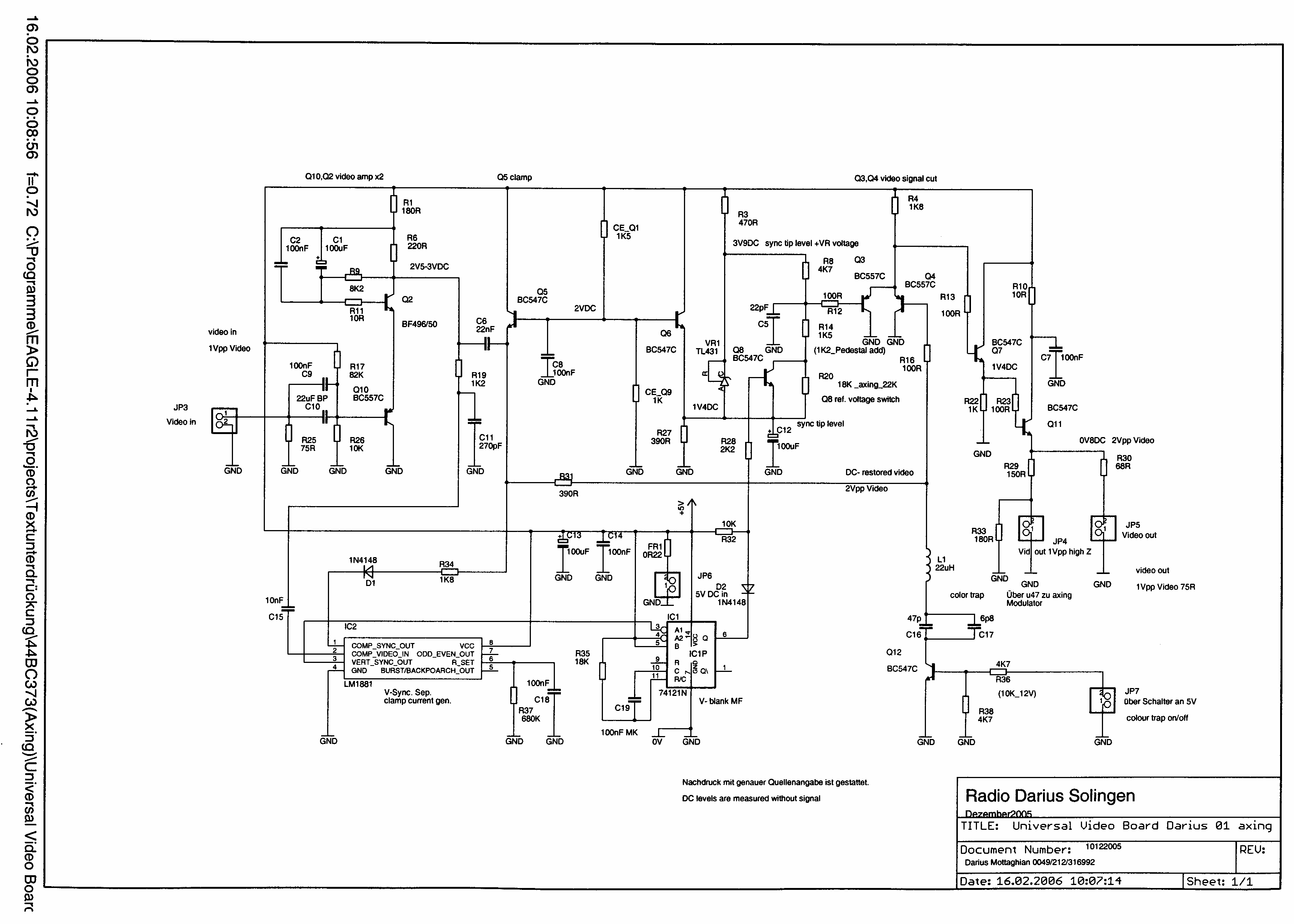
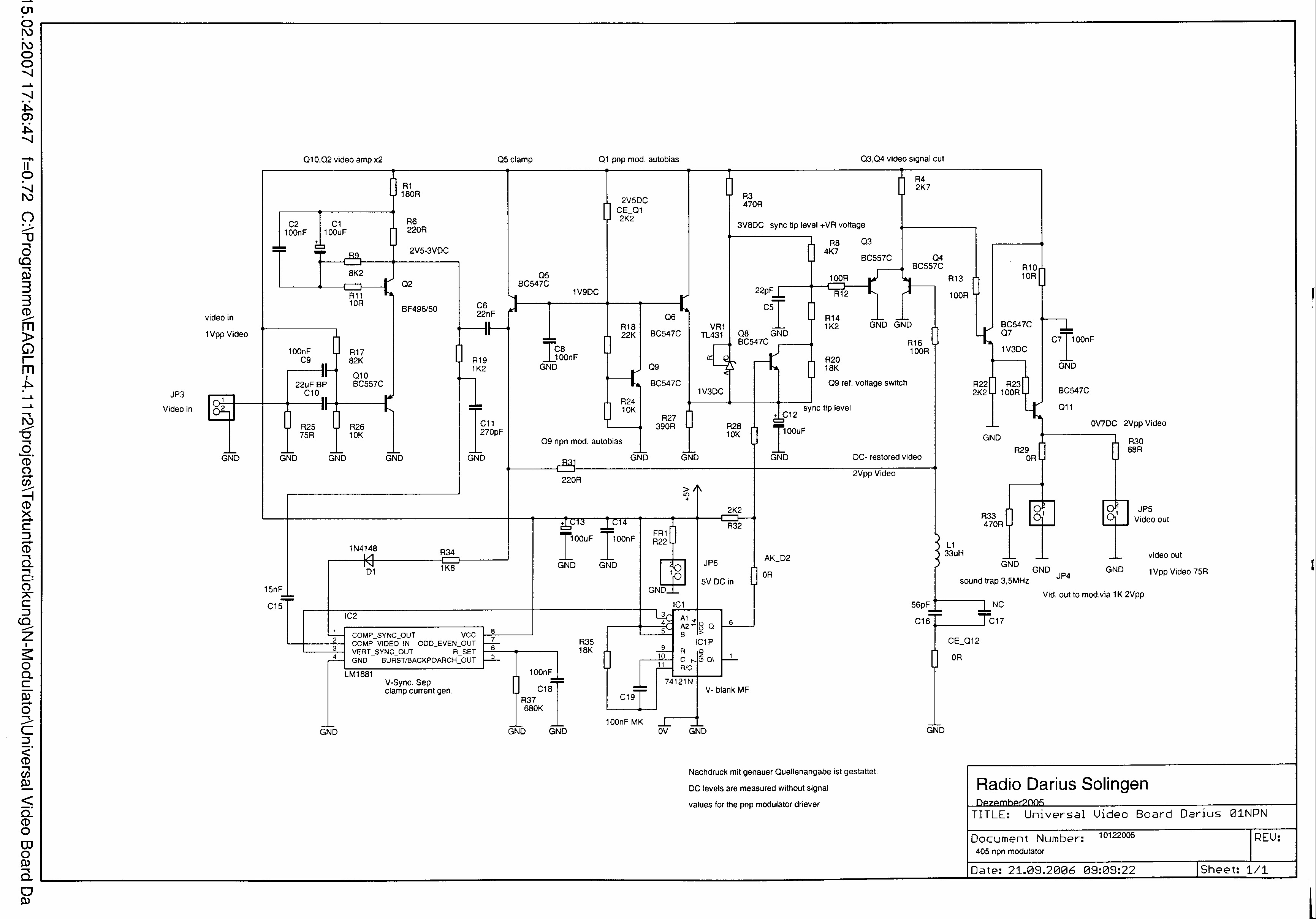
 The vision input is terminated with 75 ohms. It is buffered by Q10 and amplified to 2Vpp
by Q2.
The vision input is terminated with 75 ohms. It is buffered by Q10 and amplified to 2Vpp
by Q2.
The LM1881 is a sync separator. During the sync tips the clamp current flows via R34 and D1
to pin 1 of the LM1881. Q5 clamps the vision signal comeing from C6 on its emitter.
Q1 or Q9 are only loaded if a modulation transistor is driven.
The monostable makes the V pulse width longer so that output Q can supress the teletext
or generate a V pedestal. Output Q goes to 0 at the starting point of the picture.
Emitter of Q6 is on sync tip level. This is the level that the reference voltage of the bandgap IC
TL431 sits. Visionsignal components at the emitter of Q4 are cut by Q3 if they reach a higher
voltage level on base of Q4 than the voltage at base of Q3 given by the reference voltage divider
R6/R14.
When Q8 is switched on by the monostable, the divided reference voltage is 0V6 higher than
the sync tips (this is black level), thus only the sync signal is at the emitter of Q3 and Q4.
The teletext is suspressed this way.
If Q8 is open the divided reference voltage is 2V higher than the sync tips. Whitelevels more
than 100% are cut and can not cause overmodulation. (Vision in sound.)
A trap can be added by Q12. For example a color trap from pin8 of the scart connector or by
hand with a switch.
The vision signal reaches the 75 Ohms output JP5 via the emitter followers Q7 and Q11.
The signal at JP1 can drive an pnp vision negative modulator. In this case Q9 is replaced by a
resistor. An npn vision positive modulator can be connected at JP4 and Q1 must be replaced
by a resistor.
In both cases the temperature drift of the BE- junctiones is compensated automaticaly.
The values of the components depends in the applications. Look for the exact values in the
special application schematic.
UVB - Universal Video Board
- Schematics
- Calculation of the vision amp
- Parts list
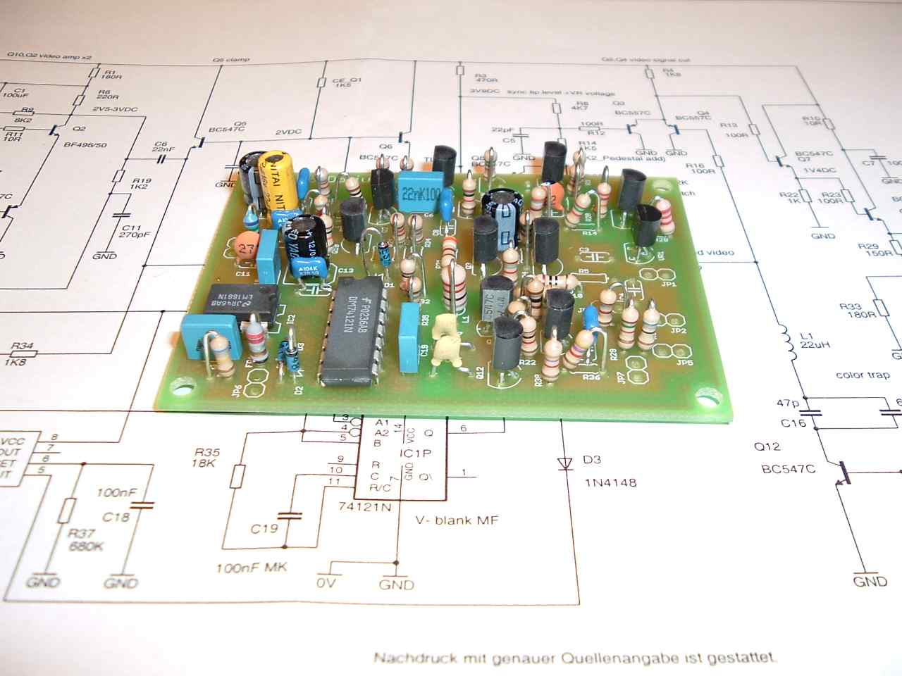
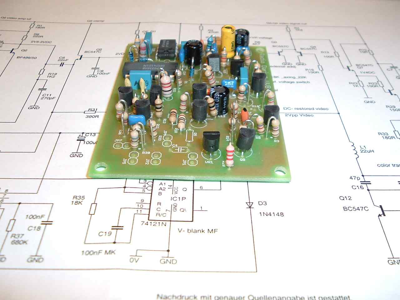
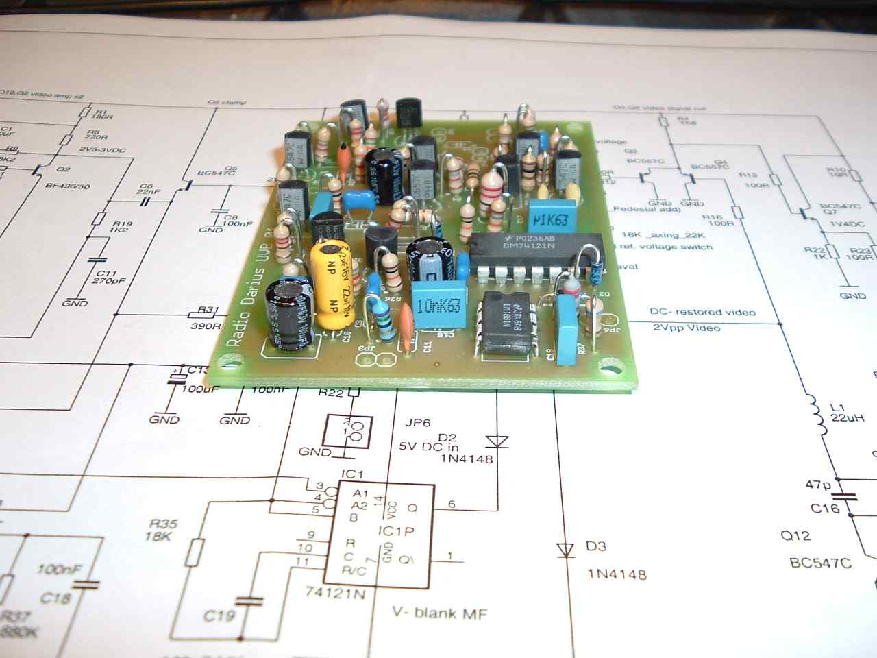
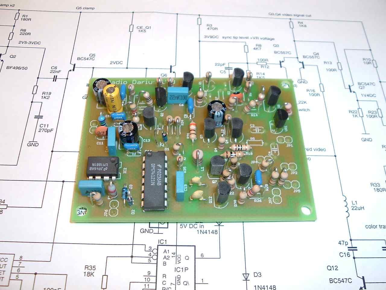
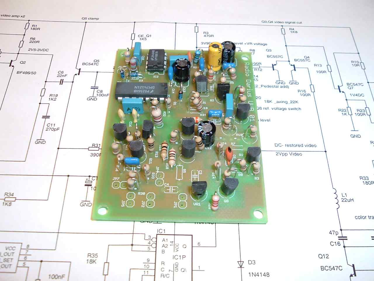
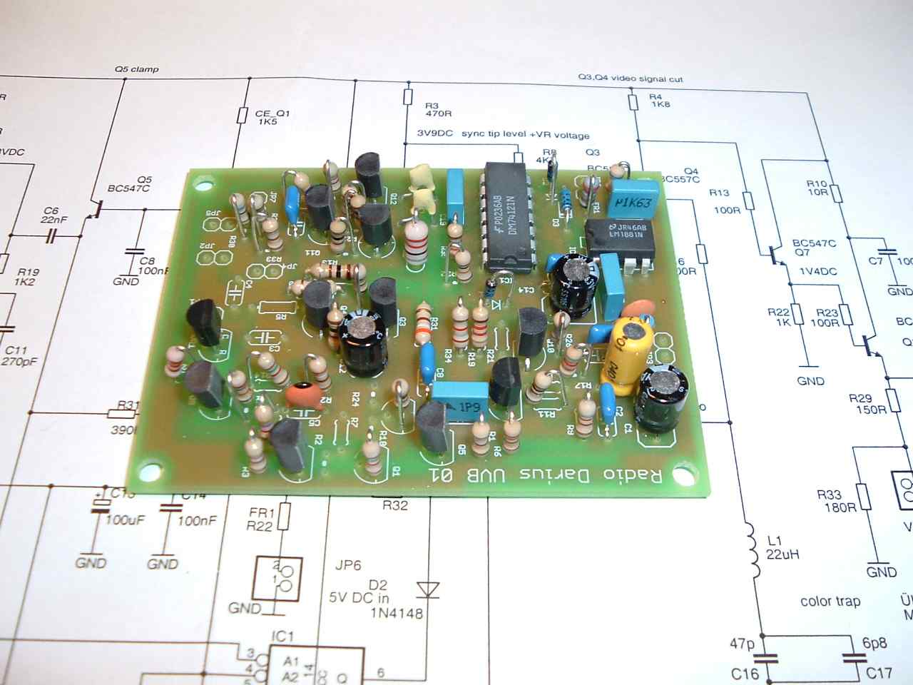
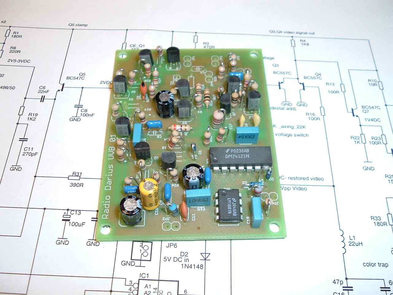
- View from above
- View from above
- View from above
- View from above
- View from above
- View from above
- View from above
- View from above
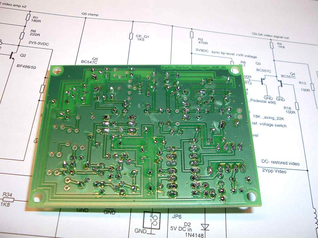
- View from the down side
- View from above
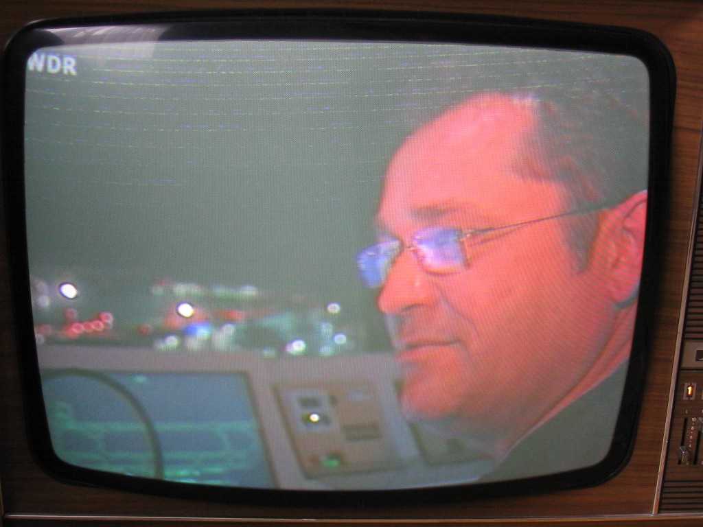
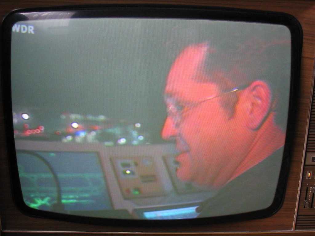
- Tesla 4001 TV set with videotext retrace lines - no UVB
- Tesla 4001 TV set with suppressed videotext retrace lines after install of the UVB
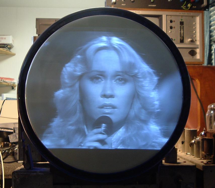
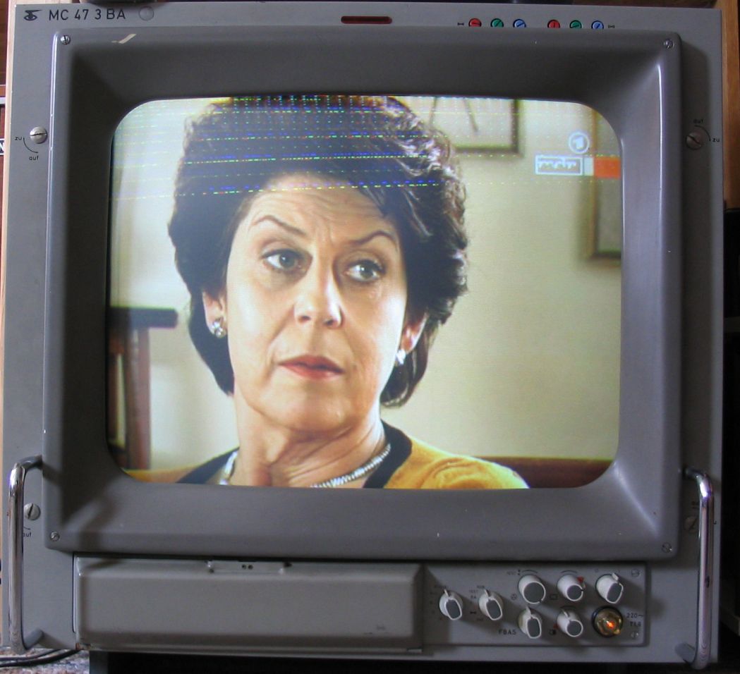
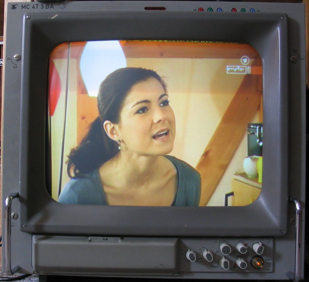
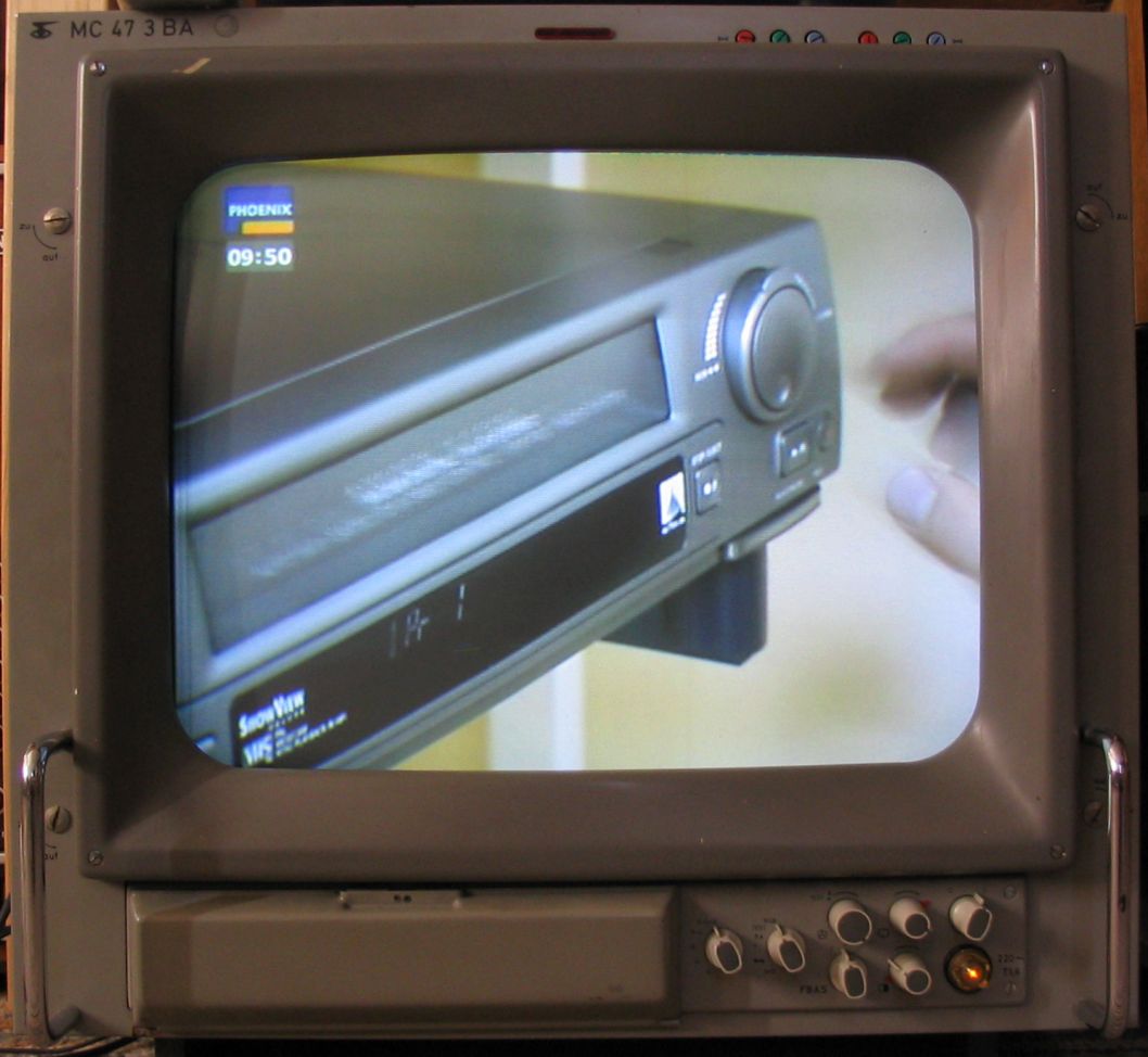
- Professional studio monitor with videotext retrace lines - no UVB
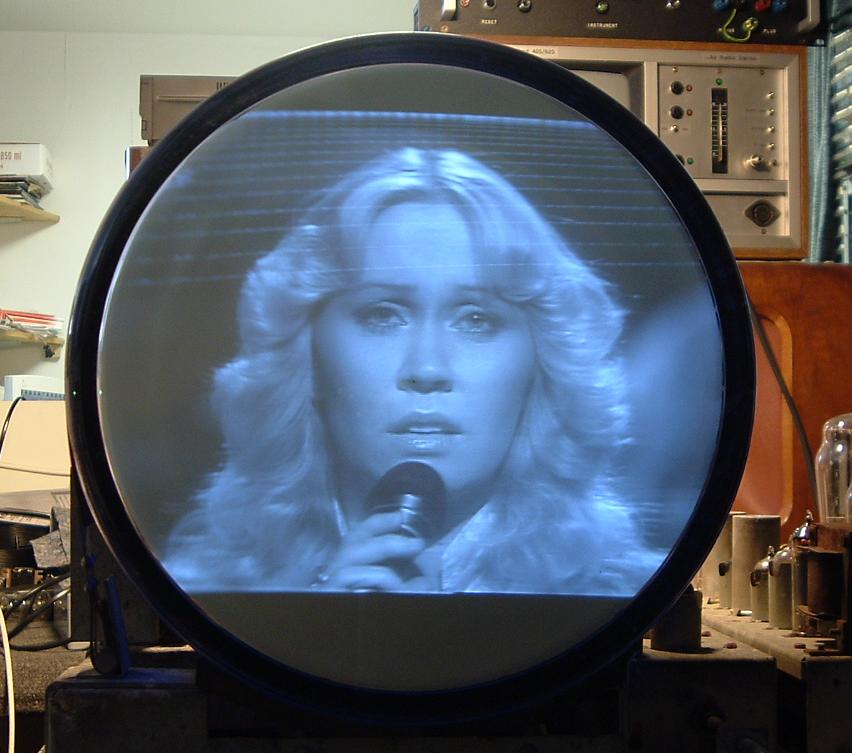
- Professional studio monitor with suppressed videotext retrace lines after install of the UVB
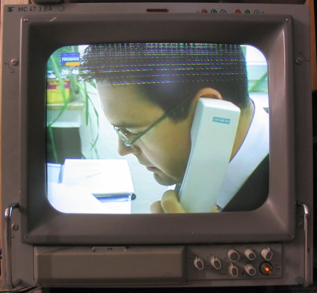
- Professional studio monitor with videotext retrace lines - no UVB
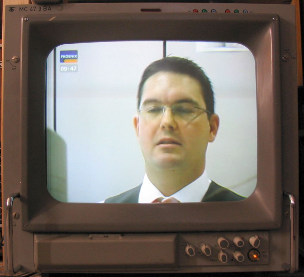
- Professional studio monitor with suppressed videotext retrace lines after install of the UVB
- Professional studio monitor with suppressed videotext retrace lines after install of the UVB
- Metz colour tv set with videotext retrace lines - no UVB
- Metz colour tv set with suppressed videotext retrace lines after install of the UVB
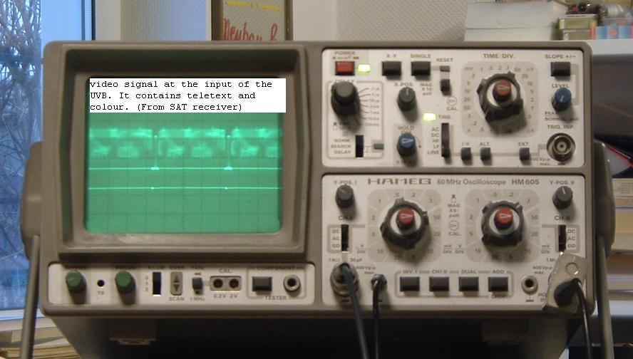
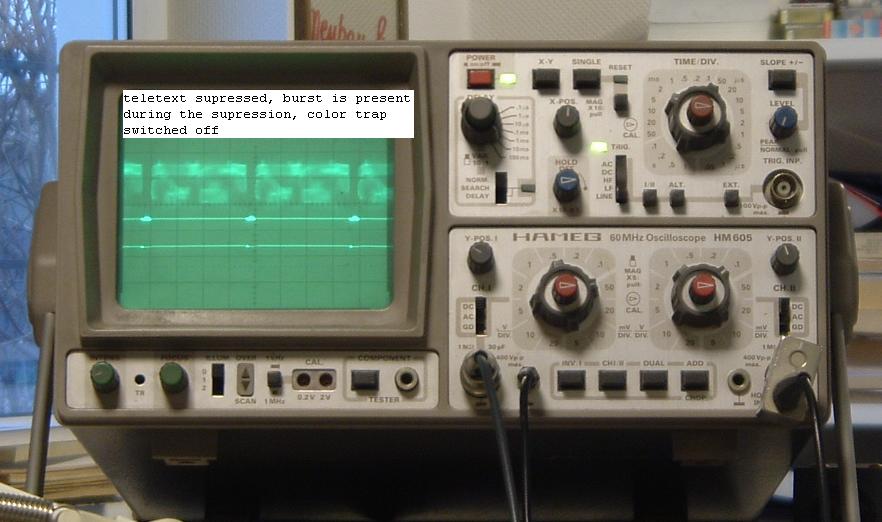
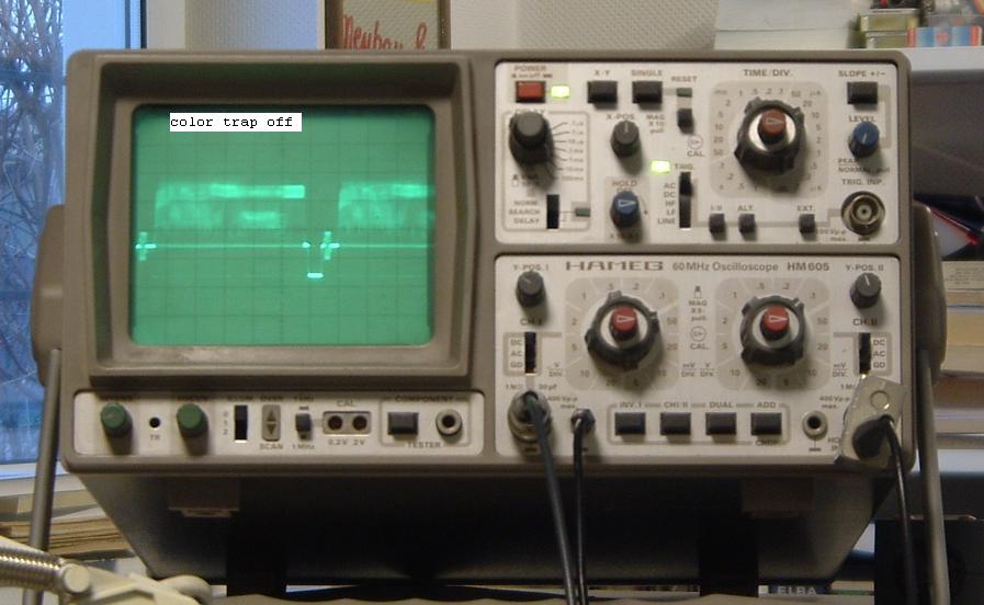
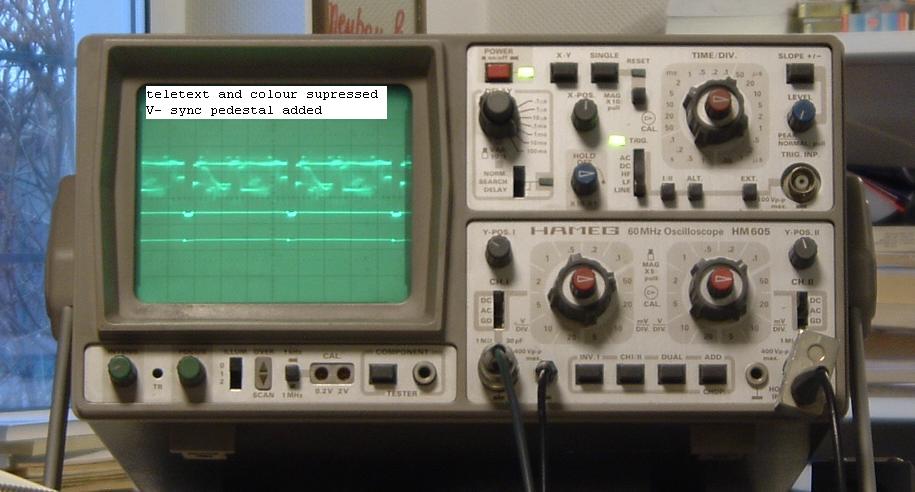
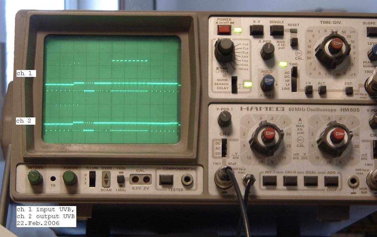
Oscillograms of video signals with and without UVB
- Teletext on
- Teletext suppressed with UVB
- Colour trap off, burst on
- Colour signal suppressed with UVB
- Teletext and colour supressed with UVB, V-sync pedestal added
- Macrovision impulses from DVD suppressed with UVB
General discription for the PNP and NPN transconductance modulators
The vision oscillator output level is approximately 500mVpp. This output is divided by a cap divider C3 (2,2pF) and C1 (27pF). The modulator transistor gets only 50mV RF between base and emitter to make sure that it operates linear! C1 is blocked to emitter to keep this voltage constant . C1 at the base and C2 (100pF) at the emitter have low impedance at RF and high impedance at vision frequencies. Thus for the RF the modulator transistor is a linear common emitter amp and for the vision it is a linear emitterfollower. At the collector output the modulator transistor is loaded with R6 (18 Ohms). With its low current the transistor generates a very low output level (70dBuV). Thus there is no significant feedback from the collector. This transistor operates nearly in short circuit at the output. To understand the mixing process it is important to know that the transconductance of a transistor is proportional to its emitter current! Its voltage gain is the transconductance multiplied by the collector output resistance. For the vision the transistor acts as an emitterfollower, thus the emitter current is proportional to the vision signal. The result is the RF level at the collector output is proportional to the vision signal and this is AM modulation! The advantage of transconductance mixing against the usual additive mixing is lower output noise but good filters at the output are still neccessary. The biasing is set by the UVB. Positive vision RF modulation is generated with an NPN modulator transistor because its emitter current is switched off at the sync tips. Negativ vision modulation is generated with an PNP type because there is maximum emitter current at the sync tips.
Photos: © Darius Mottaghian und Eckhard Etzold 2006
eMail: Email an Darius Mottaghian
Fernseher und Farbfernseher aus der Anfangzeit des Fernsehens und des Farbfernsehens
Homepage Eckhard Etzold